I published a number of keel and rudder design articles over the course of about 3 decades in magazines ranging from SAIL, Sailing World, 48 North (Seattle Sailing Local Magazine) and most recently in Professional Boat Builder. I have provided a link below to the article that I last published in Professional Boat Builder because it is the most comprehensive article of all of those that I published. I have not seen any similar set of details provided by any other author to my knowledge. While there are excellent hydrodynamic articles by well known author C J Marchaj (Aero-Hydrodynamics of Sailing – Dodd-Mead) specific details of specific foil shapes and definition of the true value and function of the once popular Winged Keels are not provided in most books.
Our WINGS and FOIL programs are designed to allow the optimization of Keels and Rudders for low speed power ( Speed to Length Ratios under 2) and sail applications. True state of the art performance analysis of Keels and rudders would require the use of 3D Computational Fluid Dynamics software and a detailed knowledge of the modeling methods needed to use the this advanced analysis software. We have endeavored to offer programs and design methods (described in the download article) that are within the grasp and financial resources of the great majority of designers and hobby builders. We recommend the more advanced software in our companion blog article on “How to Make a Good Boat Faster”.
Please consider the following article as a technical introduction to Keel and Rudder design based on well known Aero-Hydrodynamic principles. Many keels and rudders have been designed with our software that have contributed to winning major offshore Sailing races, including the Newport- Bermuda race in which a Vacanti Keel modification to a J36 resulted in an overall victory over Farr and other well known boat designs.
Once last critical thing that must be understood in Keel and Rudder design is implementation accuracy. Any keel or rudder design can be rendered useless if the actual implementation or build of the design is not done with sufficient accuracy. A good example was a keel design I created for a Six Meter Sailing yacht named Steverino. The builder of the keel did a great job but at the last minute decided that the “look” of the keel was not agreeable to him. The builder then heavily modified the intended leading edge nose of the keel by grinding the off the forward 6 inches of the leading edge into a more visually appealing (to him) rounded shape. This modification destroyed the entire foil shape structure of the keel tip design and resulted in poor performance. Similarly if good CNC or other high accuracy mold methods are not used the expected performance of the keel or rudder may be destroyed.
Boat Stability and Keel Design
While most designers worry about athwartship stability normally provided by a keel, one client and user of our software reported that he was working on a boat that had the terrible tendency to bury its bow while running downwind. We looked carefully at the choice of foil shape used on the keel and determined that it had exceptionally poor stall characteristics that could result in very high drag. While most consider the keel to operate near zero angle of attack when running downwind, the boat is constantly being steered to keep the apparent wind at the required location relative to the spinnaker and mainsail. This particular boat required that all crew remain aft in the cockpit to keep the bow up and prevent submerging in waves.
After the keel was redesigned with an appropriate foil shape, specifically designed for the Reynolds number range of that boat, the boat downwind characteristics changed dramatically. Literally the boat was “tripping” over its own keel and was being forced nose down by the large moment arm of the keel drag located well below the waterline. Many have not accepted this hypothesis but none the less, accuracy of build and proper foil shape selection (use of FOIL and WINGS) resulted in a boat that won and was sailed safely off the wind.
WINGS 10 is the NEW version of WINGS for Keel and Rudder Design NOW BEING released. It will replace all previous versions of WINGS including the current WINGS 32. The new version will include major improvements in display quality by supporting high resolution screens up to 4K. An all new Parametric Design Dialog will include a highly revised dialog screen with new input capabilities and includes an image of the keel or rudder type that is being designed via the parametric design process. The next few images show the sorts of parametric design methods we are discussing that are specific to rudder design. Keel design parametric data will also include keel bolt locations, size and material strength. All calculations are per American Bureau of Shipping for Offshore Racing Yachts. We may add CE / IMO calculations as well for stock materials and dimensions for various classes of ocean applications.
Keel or Rudder design via “parameters” (parametric design) requires the entry of a few defining overall characteristics of the keel and rudder so that WINGS 10 can automatically create a preliminary design and draw it for the user instantly. This allows for the very rapid creation of a design without the tedious entry of individual curves, lines, corners etc that many CAD tools are based on. All of our Vacanti Yacht Design LLC software tools are based on the parametric design concept. Programs like WINGS then offer detailed editing tools that permit the detailed refinement of the original Parametric design to meet specific needs. This allows infinite design variation and optimization.
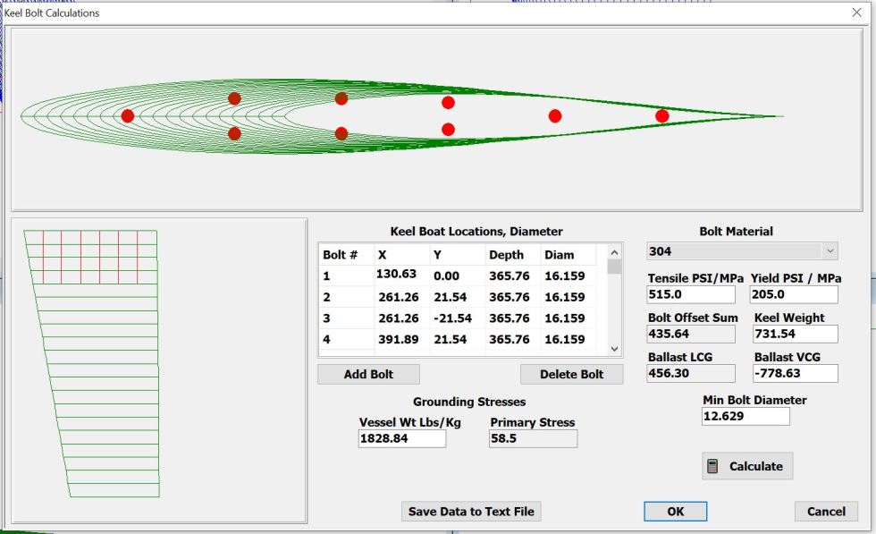
WINGS 10 now includes Keel Bolt Design Capability and provides required minimum bolt diameter per 2021 ABS Rules for Offshore Sailing Yachts. The image below shows a standard fin keel with bolts drawn per diameter and per location in the bolt table. Depth of the bolt is shown in the PROFILE view below left.
WINGS 10 computes the required minimum bolt diameter based on keel weight, center of gravity, bolt locations and choice of steel for the bolts. A list of 24 Steel bolt choices is provided that ranges from Aqualoy to Stainless 304 and beyond. User can enter Mass of the vessel for use in computing grounding stress per ABS rules, Pressing Calculate button updates all bolt locations in the drawings and computes new stresses and min bolt diameter at base of thread depth. A Text Data file for all bolt and material information is recorded for use in implementation of the keel.
Flanged Keel Design Bolt Placement
WINGS retains the same NURB (Non-Uniform Rational B-Spline) surface design that we made popular in PROLINES. The only imitation to the NURB surface is that we enforce the aerodynamic shape of the foils (NACA 00, 63, 64, 65, 66 Series and custom foils designed in FOIL 10). Other than that the overall shape and thickness distribution is entirely editable by the user.
WINGS 10 Keel Rendered with WIN 10 Built in Tools
WINGS 10 retains the ability to use any combination of foil shapes to achieve a desired volume distribution along the span of keels in particular. While it is not likely that a rudder might use more than one foil type a user many also modify the placement of any number of foil shapes as a function of span.
WINGS 10 will include the new STL (Stereo Lithography) file format that is now available in the PRO version of PROLINES 8. This STL file will permit 3D printing of scale models of keels and rudders, export to hull drag analysis packages such as HydroComp NavCad and permit 3D CNC machining of molds or finish milling for Keel and rudder manufacturing. STL files can also be used for photo realistic rendering of any keel or rudder design.
WINGS 10 Now Directly Calls WIN 10 Rendering Tools
We are also working on new Rudder Design features such as rudder stock thickness distribution and rudder torque and bending calculations to permit safe design of steering gear and rudder stock material selection.
We invite comments and suggestions for desired WINGS 10 features and reports of existing bugs or fixes that may be needed in WINGS 32 so that we can address those issues before WINGS 10 release.
Cheers and all the best in Keel and Rudder design!
We have received some requests for changes and improvements to PROLINES 8 (all versions) that include use of the mouse wheel for zoom control in any view (once a view is active) and ability to rotate the perspective view by holding the Left Mouse button down and dragging. Both of these concepts are under review for incorporation in a future release of PROLINES 8.
We are also currently working on changes to the initial Parametric Design for a new Hull Design. We have added a new Catamaran Hull type that allows for the instant creation of a dual hull catamaran for power or sail. This new hull type will require changes to Hydrostatics and Stability calculations before it can be released. This is a significant change and will require considerable work to validate all calculations before the new version is released.
We are also considering the addition of a body view image of the selected hull type during the parametric hull design (File, New…) design dialog. This will better indicate the basic shape of the hull type that is being designed.
We plan other changes to PROLINES existing fairing tools to offer easier to use and understand data plots of curvature or slope of hull shape in various planes. We have already heavily improved the Edit, Visual Vertex feature in PROLINES and may add capability there as well.
Please write and send us your concepts for PROLINES features or comment on any issue you have found so that we can correct any errors.
Cheers and all the best for great boat/ yacht / ship designs with PROLINES.
As of October 31, 2020 Vacanti Yacht Design LLC will no longer honor requests for License Keys or technical support for any version of PROLINES, LOFT 2011, FOIL 5 or older other than PROLINES 8, WINGS 10 and FOIL 10. All previous versions of PROLINES 5 (DOS), PROLINES 6 (Windows 3 Thru Windows XP) and PROLINES 98 or PROLINES 7, FOIL 5 and older will be obsolete. Due to changes in Windows operating systems 7,8 and 10 we can no longer offer support for these older versions of PROLINES, LOFT and FOIL.
We do offer low cost upgrades for each version of PROLINES, LOFT and FOIL that have been designed for Windows 7, 8 10 and beyond. We know that there are thousands of users of the older versions of PROLINES, WINGS and FOIL so we make an unlimited offer for an upgrade to the new version of PROLINES , WINGS or FOIL that will not expire with time.
In addition to adopting new Windows 10 technology features, PROLINES 8 now includes many new features for editing, new 3D CAD file export, direct integration with HydroComp NavCad that is an excellent Propulsion analysis tool for all PROLINES hull designs. Many more features will continue to be added to PROLINES 8 at no cost to existing owners of PROLINES 8. We encourage you to consider upgrading soon. WINGS 10 will also include STL file export as well as many other new features.
November 2020 Update on WINGS 32 / WINGS 10.
WINGS 10 is currently still in development with many major new features being installed and tested. New features include ABS calculations for Rudder Stock and Keel Bolts, Improved Parametric design tools, Improved display and tools and support for very high resolution 4K screens. WINGS 10 will offer separate parametric design entries for rudders and keels and separate hydrostatics calculations.
We will support WINGS 32 owners until WINGS 10 is released. No further unlock codes or other technical support will be provided for WINGS 32 once WINGS 10 is released.
New PROLINES, WINGS, FOIL Features Solicited
We encourage you to contact us and send requests for new features that could potentially be added to our software. Please us a Contact Us form to send your suggestions.
I have worked in radar technology for over 44 years in application to military missiles, radar altimeters, aviation weather radar and small phased array systems for drone collision avoidance, mapping radar Altimeters and brown out landing aids for helicopters.
I’ve watched as recreational and commercial marine radars transitioned from very high power systems ( up to 25,000 watts peak) based on nearly 80 year old magnetron transmitter technology to low power solid state radars that might transmit a mere fraction of a watt.
Solid state systems offer Doppler speed measurement to detect relative motion between the radar and other vessels. Older magnetron systems are not sufficiently stable in operating frequency to permit Doppler detection. Older magnetron tube systems transmit exceptionally short pulses at very high power. But a receiver designed to collect those very short pulses must have a very wide bandwidth that includes competing noise. Solid state systems transmit far longer pulses that are typically encoded with linear frequency modulation called “chirp”. The combination of a long pulse that allows a narrow bandwidth receiver with far less noise results in greater detection range per watt of transmit power. The encoded frequency chirp achieves fine range resolution. Low power solid state systems can also use very short pulses for very fine resolution short range detection to a fraction of a mile.
Therefore newer solid state systems from Raymarine, Navico, Garmin and Furuno offer excellent performance in open array scanner systems and fine performance in small dome packages. These systems have virtually standardized on Ethernet digital data and simple 12 to 24vdc power.
With the advent of low power transmitters radiating less than 0.1% of the power of some older radars, the danger of suffering physical damage to eyes due to microwave heating has all but been eliminated.
Only the Navico Broadband Radar employs FMCW modulation and radiates less than a watt of power. This system enjoys favor with small boats where use is confined to 5 Nmi or less. In places like the San Juan Islands of Washington and the Gulf Islands of Canadian British Columbia that is more than sufficient for collision avoidance.
FMCW or Frequency Modulation Continuous Wave is a very powerful radar scheme when properly implemented. I have several patents related to this technology that includes new products currently in production as radar Altimeters and Millimeterwave Phased Array Radar.
A PDF presentation on recreational marine Radar will be added to this blog in the near future. The file includes more on radar modulation technology, installation advice, complimentary functionality with AIS and much more.
Contact us for consulting on marine Radar selection, site selection for optimal performance and comments on radar technology in general related to marine applications.
August in the San Juan Islands brings warm weather, light winds and opportunity for enjoying the best of boat types. Our style is a North Pacific 39 pilot house trawler. Speeds to 9.5 knots but cruise at 8 allows needing just an hour or two to reach most destinations and up to 4 hours for longer trips. Many enjoy high speed cruisers that run in the teens and near 20kts. But they can leave huge wakes and cause problems for shorelines and other boaters.
Anchorages are protected and beautiful in the San Juan’s. Plenty of room for lots of boats of every description. The beautiful area compliments some lovely boats as well.
In these COVID19 days people are friendly and mutually respectful wearing masks when gathered on trails or small stores for supplies.
Shaw Island General Store has a long history and is the center of traffic on and off the island with a Washington state ferry terminal adjacent to the store.
Local Dungeness crab is a delicacy alone or added to any meal. Crab is readily caught with traps and requires little cleaning before being prepared for dining.
Choosing the right anchorage is critical to a good night’s rest when winds in the nearby Strait of Juan de Fuca can reach 30 knots overnight usually WSW but can become southerly and spread among the islands. Steep chop spaced close together can challenge any boat design at rest or underway.
Having boated in the Pacific Northwest for over 30 years on 4 boats we owned and others we chartered has lead to an appreciation for many boat types and concerns about others.
Early mornings frequently are accompanied by ribbons of fog. As the sun rises it burns off and is replaced by warm sun and modest breezes.
Anchored in Parks Bay a research preserve on SW Shaw Island
The forecast is for rain and wind late tonight. So boats have gathered in Parks Bay to gain protection from expected strong Southerly and South westerly winds. The bay is open to the North but tall trees and rising hillside provide protection.
UW Research Dock
The south end of the bay shallows slowly after much of the bay is 45 feet deep. At the head of the bay a UW Research dock is graced by an older trawler that likely transports staff to and from nearby Friday Harbor where a large research facility is installed.
The head of the bay shallows to a more useful 20 to 25ft for anchoring.
High thin clouds and a steeply dropping barometer portends change is coming. In 72 hours the calm should return.
Sunset at Parks Bay
Sunset with gathering clouds was followed by a wonderful peaceful night with no wind in the bay despite a strong WSW wind blowing in the Strait of Juan de Fuca just a few miles south.
Early morning brought steady cool rain that ended just before departure at 9 AM for Island Marine Center in Fishermen’s Bay just 7 Nmi to the SE.
Our trip to Fisherman’s Bay on Lopez Island with a squall arriving was complicated by shoal draft of barely 5 ft at low tide in the serpentine entrance channel to the bay. Clearly we needed to plan for tide and wind conditions when choosing a departure time. We consulted our subscription to PredictWind weather service to note that winds would be lighter before 10 AM and that tides provided by Navionics charts confirmed a 10 AM arrival would be safest to navigate the entrance channel.
Entrance Channel
Planning was important because those 7 miles cross San Juan channel and are open to the wind from the adjacent Strait of Juan de Fuca.
Our planning proved accurate as winds were modest and depth in the approach channel was excellent. Shortly after our arrival winds increased dramatically and have been blowing well over 20 and gusting 28.
Wind in the harbor
Mostly clear blue skies accompanied the wind all day
Lopez Island looking West
Friday promises calm winds and a chance to explore nearby anchorages.
Learn how to use PROLINES for fast and easy development of a boat, yacht, ship, SUP, Canoe or Kayak! PROLINES uses powerful NURB mathematics to instantly create a full 3D Hull shape from a few basic values for Length, Width (Beam) and depth (Draft) of the boat you want to design.
Watch our Blog Section for information on Boating in the Pacific Northwest, Marine Radar and AIS and Progress on any of our software products
WINGS 10 Released this week!
WINGS 10 now includes Rudder Stock Design and Analysis per ABS Rules and Keel Bolt Design and Analysis Per 2021 ABS Rules as well. Full graphical display of the chosen rudder stock and rudder or keel bolt pattern and bolt locations is provided in both cases. Now designers can not only create CAD files and compute LIFT / Drag and hydrostatics analysis for Keels and Rudders they can also generate required installation hardware information for both Keels and Rudders. This makes WINGS 10 substantially more useful than any previous version and serves the needs of Professionals and Home Builders alike. WINGS 10 now also includes full 3D Realistic Rendering using WIN 10 tools directly within WINGS 10. With this release any user who has purchased WINGS 32 after November 11, 2020 is entitled to a free upgrade to WINGS 10.
We are also working on B-PLATES and ABS Construct versions for release and use with the new PROLINES 8 Rx.x editions (Basic, PRO and Student)
PROLINES 6, 98, 7, LOFT 2011 and older, FOIL 5 and older are now obsolete and are no longer supported. We encourage users of these programs that have been around for 10 to 20 years to consider upgrading to PROLINES 8, LOFT 2018 and FOIL 10 that offer many new features and will operate on WIN 10 and later.
The term CFD is showing up more often these days in articles describing the design efforts used to make Volvo 60 round the world racers and America’s Cup yachts faster. Computational Fluid Dynamics or CFD actually covers a great many engineering specialties and is not the sole domain of boat and ship design. In this article we will review what types of CFD products exist and hopefully provide some understanding of when and how CFD products are best suited to a project.
Computational Fluid Dynamics is the application of computers to the modeling of fluid characteristics when either the fluid is in motion or when an object disturbs a fluid. A few examples of a fluid in motion are water or chemical flow in pipes, heating and ventilation systems conducting cooling, heating or fresh air supplies to a building. Fluids in motion also include flame and fire effects in combustion or jet engines. Surprised by these fields of interest?
What about examples of an object disturbing a fluid? Examples include stirring paddles submerged in a tank of water and effluent in a waste treatment plant, aircraft of all kinds, cars and trucks at highway or racing speeds and even monohull sailboats, ship, multihull sailboats to name but a few.
Obviously, an open mind is important when considering what constitutes a fluid. Fluids can exist in gaseous and liquid states and science has recently found that even some solids can exhibit fluid like characteristics under right conditions. Scientists have found that some of the most spectacular and deadly landslides or rock falls behave as a fluid while the mass of stone and soil or sand is in motion, only to return to a most decidedly solid form when the motion subsides.
The general field of fluid dynamics differs from the field of boat design in one critical way. Only boat design deals with a vehicle passing through the two fluids of air and water simultaneously.
Our atmosphere is a compressible fluid, though not at yachting or even high-powered boat racing speeds. Air can change in density according to altitude, temperature and humidity. Water is an incompressible fluid that can vary in viscosity according to its salinity and temperature.
For most of us, small effects such as variable salinity and temperature are not of concern, but can make the difference between winning and loosing a major international yacht race.
How do CFD programs Work?
CFD programs are based on the laws of physics, such as the law of conservation of momentum, and special “boundary conditions”. The law of conservation of momentum states that the total momentum of a system remains constant regardless of how the system may change. A boundary condition limits how and where a fluid can travel. A simple example is that motion of the fluid must remain tangent or parallel to the surface of an object passing through it. Another example is that pressure applied by the fluid against the object must be perpendicular to the surface at all points.
These laws and conditions are critical to the development of a CFD program because they allow an aerodynamicist to write equations that describe the system that is being studied. Without the physical laws and boundary conditions there would be no way to write equations that describe fluid motion. The complex equations that result take into account the viscosity, mass and other characteristics of the fluid. The equations are written using integral and differential calculus and require specialized computer techniques to solve them. Typically the programmer writes an algorithm that makes a series of estimates using algorithms that iteratively solve the sets of equations by looking for “balance” in the system of equations. A final answer is obtained when the algorithm converges on a solution with an error that is sufficiently small for the desired accuracy.
Once an algorithm has been developed to implement the laws of momentum and boundary conditions, it cannot be applied to the entire surface of the hull and appendages at once. The surface area of the hull, keel and rudder are broken into thousands of small patches (collectively called a mesh) and the algorithm applied to each patch. Each patch in turn influences the fluid flow on the patch area of its neighbors and therefore the solution must account for the conditions surrounding the patch currently being solved. As a result the program must solve and resolve the equations for all of the patches until the solution obeys the physical laws and boundary conditions.
Sometimes the complexities of the laws of physics are too difficult to implement all at the same time. As a result the aerodynamicists choose to write programs that make certain limiting assumptions that permit the programming to become more practical and still result in reasonable results. A specific example arises in the case of what actually happens to fluids very near the surface of an object. The boundary layer as it is called experiences shear forces in the objects direction of travel that result in viscous drag. These shear forces are described in a special set of equations called the Navier Stokes relationships. The Navier Stokes equations are sufficiently complex themselves that attempting to include them within every aerodynamics or hydrodynamics program would make the solutions nearly impossible. As a result there are Navier Stokes based programs that specifically address viscous drag and Panel method programs that compute lift, wave drag and induced drag. A complete estimate of the drag encountered by a boat requires the data supplied by both programs.
What do CFD programs Calculate?
The most obvious calculation that would be of interest in boat design is the determination of drag forces. But drag comes in several forms that can include, wave, viscous, and induced drag. Therefore, a designer must evaluate the effects of his design in each of these drag areas. The second general area of calculation is lift. The term lift arises from its application to aircraft and becomes a bit confusing when applied to the field of boat design. Lift applies to the forces generated by a keel or centerboard to resist the side force of sails and the driving force of the sails themselves. It also applies to the turning forces of a rudder, and the supportive force acting on “foils” to elevate a hydrofoil sail or powerboat above the water surface.
There is also a distinction between 2 and 3 dimensional fluid dynamics analysis. Specifically, there are programs that predict the performance of foils as if they existed on a wing of infinite length. Here the term “foil” is used to define the shape of a keel or rudder along the chord from the leading to the trailing edge. Foil shapes are best known by the alphanumerical names given to them such as NACA 63A012. So a 2D fluids program would compute the lift, drag, velocity distribution, turbulence onset and the generation of bubbles similar to cavitation for a 2D shape such as a wing or keel foil, and would not include any 3D information such as keel span or thickness distribution or the presence of a bulb. A 3D fluids program would compute wave and induced drag from a hull, keel and rudder, including the effects of a bulbed keel carrying winglets.
CFD codes are critical for more than optimizing the performance of a top-notch America’s Cup class racing yacht. These codes can be of great value to determine loads placed on boat structures of all types and are invaluable when applied to unique marine structures such as oil platforms that are frequently subjected to the world’s worst storms.
Lift and drag effects translate directly into loads that must be sustained by the boat or oil derrick if it is to remain intact in its intended operational conditions. For example, several years ago when the race was known as the Whitbread Round The World Race, many boats developed life threatening hull delamination when subjected to the continuous pounding of high speed downwind surfing and upwind beating. While delamination of a boat at sea is definitely related to structural design errors, those errors were caused by a lack of detailed information about the fluid forces experienced by the boats. Knowledge of these forces would have enabled designers to prevent the hull damage in the first place.
Therefore, the potential application of CFD to your design project should depend on whether or not the design regime that your vessel will operate in has well understood engineering data available to prevent hull damage in addition to overall performance of the vessel. For example, the last few years have seen the development of high-speed hydrofoil sailboats for the consumer market. These top performance boats experience not only significant speeds and loads, but the potential for unstable characteristics could make it highly dangerous to ride in one. However, the judicious use of field-testing and computer analysis has produced a crop of very exciting hydrofoil sport boats that are a joy to fly in.
Finally, several years ago a multihull sailboat arrived in port after participating in a trans-Atlantic race. When the centerboards were raised in the outer hulls of the trimaran, the skipper was
shocked to learn that the boards had been sheered off just below hull depth and he had not had their use for some indeterminate time during the later portion of the race. Clearly, the structural design of the boards had not taken into account the true forces of lift, drag or perhaps cavitation that would be experienced at sea.
CFD programs do not calculate how fast a boat of any type will pass through the water or predict the time to complete a course around the buoys. Predicting speed on a racecourse is the domain of another class of programs called Velocity Prediction Programs or VPP. The VPP makes use of lift and drag numbers calculated in a CFD program to estimate the speed about will sail a course given the sail drive forces and the stability or righting moment of the hull. The VPP is a closed loop simulation continuously varies estimated speed and resulting lift, drag and righting forces until retarding and driving forces are balanced and a stable speed results. A CFD program on the other hand is an open loop simulation that simply states that given an angle of heel and speed for a specified hull and appendage configuration, here are the forces that will result for that instant in time. No consideration is given to how the vessel achieved that speed or sailing condition.
In summary then, CFD programs not only calculate lift and drag forces of a hull with appendages, they can also be used to compute pressure loads due to waves and wave impact at speed. The forces of lift, drag and pressure can be translated into structural requirements and provide the means to optimize a hull working in concert with its appendages to produce lift in the most efficient manner possible while satisfying the needs for stability. Predictions of lift and drag at various speeds can be used to develop a mathematical model needed to accurately close the analysis loop of a velocity prediction program.
When is a CFD Computer Program Required?
CFD codes are not always required or justified however, when simpler means of estimating the forces involved are available. In the case of a typical sailboat design, the forces generated by the keel and rudder can be easily estimated if the keel lacks a bulb and if the keel and rudder shape are essentially straight leading and trailing edges. It is possible to make use of analytical methods that are easily implemented on personal computers. A simple example is the program I wrote called LOFT that makes use of analytical methods developed by NASA and the US Air Force for initial performance prediction of wing designs.
However, while simple programs like LOFT can adequately address typical bulb-less keels and rudders they cannot analyze the performance of an America’s Cup racing keel with bulb and winglets. Only 3D CFD programs can address that complex task.
Who can operate a CFD program?
While CFD programs can be of tremendous value, getting accurate and meaningful results is not typically within the reach of amateur and many professional boat designers. A degreed Naval Architect or a fluids dynamicist is required to generate the key initial input to a CFD program called a mesh.
The mesh is a mathematical description of the hull and appendages that are to be analyzed. It is not sufficient or even possible to use standard stations, waterlines and buttocks as inputs to a CFD program. The detailed shapes of the hull and appendages must be defined by a mesh of square
patches that adjoin one another and whose dimensions are chosen according to the local curvature of the hull or appendage or by the occurrence of the intersection of the hull and a keel, rudder or lifting strut of a hydrofoil. The generation of a mesh is a science unto itself and can require iterations by the analysts running successive trials to be sure that the mesh is sufficiently dense in critical areas. Some meshing can be done automatically and then refined by hand.
Typically the developers run complex 3D CFD programs or those trained in their use and as result are not really meant for use by the rest of us. However, 2D fluids programs designed for the analysis and development of 2D air or hydrofoil shapes (recall the 63A010 example) are sufficiently easy to use for a designer with basic mathematics skills and general knowledge of airfoil characteristics. Analytical programs such as Vacanti Yacht Design’s FOIL program can aero / hydrofoil lift, drag, turbulence onset and bubble formation characteristics for anyone with basic computer skills and a working knowledge of basic foil design.
What CFD Programs Exist?
Panel Method and Navier Stokes programs are two general classes of CFD programs that apply to the issues of boat design. The most commonly used and most available are Panel Method
programs. Panel methods allow the prediction of wave drag, free surface effects and induced drag due to lift generated by a keel or rudder but they do not account for viscous drag. Programs using panel methods assume that there are only forces normal to the surface of the hull within the fluid. However, due to viscosity, the fluid is subject to forces in shear – more or less parallel to the hull surface that causes turbulence. Therefore the panel programs are referred to as “inviscid” analysis methods. As a result they compute wave and induced drag but not the effects of viscous drag. Viscous drag computations are computed by specialized codes known as Navier Stokes programs. These programs are difficult to use and apply and are best left to a professional skilled in their use.
When a designer has a task that justifies the use of CFD programs, he should be using design tools that that can export true 3D surface shapes in the form of common Computer Aided Design (CAD) file formats. Designing in a typical CAD program such as AutoCAD using lines and polylines, even though in 3D are not sufficient for use with CFD programs. True surface definitions such as Non-Uniform Rational B-spline (NURB) surfaces are required. Most professional versions of the commonly known yacht design programs (AeroHydro, AutoShip, Maxsurf, New Wave, PROLINES) all provide this kind of file exchange.
Licensing costs or consulting time is available from the companies or sources listed below.
Company Name
Program(s)
Web Address
Specialized consulting companies include:
Bruce Rosen South Bay Simulations 44 Sumpwams Ave Babylon, NY 11702 631 587 3770, brosen@panix.com
Joe Laisoa Fluid Motion Analysis Consulting, Inc. 3062 Queensberry Dr. Huntingtown, MD 20639, 410 535 0307 X3351, laiosa@panix.com
Conclusion
CFD programs are best applied when there are either significant engineering unknown effects or load levels or where design optimization for a specific application in specific conditions are essential to the goal. For instance, there are many books of scantlings or building standards for typical sailboat or powerboat designs intended for inland cruising. But an attempt at the world record speed sailing at the “ditch” in France at speeds approaching 50 knots clearly calls for specialized analysis to prevent catastrophic failure that could risk lives or incur that last bit of drag that could prevent success in inching the speed record that much higher.
Some CFD codes are only usable in the hands of a skilled practioner and others are designed and intended for use by those with reasonable technical skills and willingness to do a bit of reading or research to help them understand the results and limitations of their modeling efforts. CFD and
analytical programs are very important to the development of high performance vessels from the perspective of optimization for speed and safety. High speed sailing craft and those destined for offshore use can benefit the most from computer analysis methods. One final key point here is that we have only discussed vessels in displacement mode and have not referred to high performance planning powerboats. The prediction of planning vessel performance is an art unto itself and is the domain of yet another class of programs. I refer those of you who wish to know more about that subject area to research the Society of Naval Architects and Marine Engineers (http://www.sname.org) web site.


You must be logged in to post a comment.