Contrada Crete was founded as a Farm to Table Restaurant in Valledolmo Sicily by Rossella Battaglia in 2019. The new restaurant offers the very best in fresh local foods prepared by a Sicilian Chef. This very special Restaurant has high social values as seen in this quote from the Contrada Crete “Our Values” Page:
TRUST
Relationships are built through a mutual exchange; we cultivate trust as a fundamental value with both our customers and our suppliers.
We source raw materials from local and Sicilian producers; in this way, we can guarantee a high quality standard to our customers.
If you plan to stay for more than a day or two Contrada Crete offers multiday adventures as well. Consider a 3 day stay in Valledolmo and experience the true nature of living in this lovely mountain town. Find more details here: https://www.contradacrete.com/multi-day-programs/live-the-town-life/
Available for a 5 day immersive stay in Valledolmo? Then consider becoming an honorary Sicilian!! Contrada Crete offers five days of immersion in local foods and local living style in and around Valledolmo. Write to Rossella and her team at this link and learn far more. https://www.contradacrete.com/multi-day-programs/become-sicilian/
A small sample of the delicious meals prepared at Contrada Crete:
If you are planning a trip to Valledolmo to find relatives or just experience the town of your family heritage or just visiting rural Sicily be sure to book a meal at Contrada Crete for a wonderful true Sicilian Heritage meal made from locally sourced ingredients. Note that Contrada Crete is also prepared to help with special dietary restrictions for visitors. Contact the restaurant via the main webpage Contact information for specific help with dietary limitations.
A meal at Contrada Crete will make your visit to Valledolmo into a very special memory!
Many of the visitors to Vacanti Yacht Design LLC website may well wonder about our Vacanti name being at least Italian in origin. In fact it is actually Sicilian as both sides of my family emigrated from the small town of Valledolmo Sicily along with about 3000 other people from the same town to the US about 1895. Nearly all of these immigrants to the USA settled in the farming country of Western New York State between Rochester, NY and Erie PA.
UPDATE JULY 1,2024
We are very excited to announce the opening of Contrada Crete the new farm to table restaurant by Rosella Battaglia of Valledolmo. Rosella plans to open for business mid-July 2024.
The restaurant will focus on locally grown food supplies and is especially proud to offer menu items for people with severe food allergies.
Please visit www.contradacrete.com for pictures, location, menu and hours of operation.
Rosella has been helped by family and dear friends to make this long planned dream a reality.
We are very excited and very strongly support Rosella in her new restaurant Contrada Crete!
LIMITS OF USE OF THIS BLOG
The blog is a personal one and is intended primarily for the use of our extended family so that they may see what we saw and possibly consider a trip to Valledolmo as well. This posting is covered by Copyright Vacanti Yacht Design LLC and is not intended for use by any commercial entity.
There have been a number of American families, who are descendants of the original 19th Century immigrants who have made the trek back to Valledolmo Sicily, Italy to see if they can find connections to their past or at least see where their families began. This Blog post will detail a recent trip we took to Valledolmo in Early June 2022.
We were privileged to visit this lovely farming town in June of 2022. We re-discovered the warmth and charm we have always known among our US family members among the people we met in Valledolmo. We also discovered that the town is well known for a special type of tomato, wine (White, sparkling and red), excellent Pasta, Lentils and other produce.
Approach to Valledolmo!
The view below is what a visitor first sees when approaching Valledolmo from Palermo. The newly paved road made it a very easy drive and was especially wonderful to see the town from the road just outside of town. This very lovely hillside town is surrounded by pastoral scenes and state of the art Wind Farm and Solar arrays on the surrounding hills. It was a great thrill to see this place that my grandfather had described to me well over 50 years ago.
On the way to Valledolmo
Windmills On the Hills Around Valledolmo
On the way to Valledolmo!
Valledolmo Comes into View from the Road
Upon arrival in town at the Municipal Building (Town Hall) you are greeted with the scene below.
Town Hall
And the main square of the town
Main Square in Valledolmo
Our visit began as our local Sicilian Guide Silvia was joined by town representatives (Mr Orazio Pizzolanti and Rosella Battaglia). We admired the town hall and its furnishings as we were encouraged to go upstairs to the Town Hall Conference room.
On the way upstairs we tried to absorb photos of town celebrations and functions that had been captured in large photos and displayed on a square tower located in the stairwell so that it can be viewed as you ascend or descend on the stairs.
When we arrived in the council conference room we were surprised with a large spread of traditional Sicilian food that I easily recognized as being identical to what I grew up with when visiting my Grandmothers’ home. We had a chance to talk to many towns people, some of who had relatives that matched my paternal and maternal family names. It was sometimes startling to see someone who closely resembled Aunts and Uncles of my own family. Because so many people emigrated to the same area of Western NY (Dunkirk, Fredonia, Buffalo, Rochester and others) I found that the family surnames of those we met were the same as children I went to school with in Fredonia NY.
An Amazing Collection of Traditional Sicilian Family Foods were assembled as a huge surprising Welcome for us!
We had a delightful time meeting town folk and members of the town council , especially the Mayor (sitting with Italian flag colored banner) and the Council President (far left). Shirley and I are center in the photo below. I am looking closely at the plaque that was made for our visit and placed in a special velvet case.
Greeted by the Town Council with a Ceramic Plaque in memory of our visit and a very lovely flower bouquet for Shirley
Our memorial plaque,samples of Chick Peas, Lentils and Pasta from Valledolmo and the fabulous bouquet given to Shirley
We were asked to be photographed with the Mayor(center), council members. Mr Pizzolanti and Silvia (our tour guide) are shown back left. They combined with Rossella Battaglia (third from back left) to provide a very memorable experience in Valledolmo. This little town was filled with friendly, warm and welcoming people that were a great pleasure to meet.
As we sampled the great food prepared by town families, we had a chance to visit with towns people who had relatives who moved to the US in the 19th century and who had relatives with names that matched my maternal and paternal family names. It was a great thrill to wonder if I was meeting relatives of my family. As of this writing the towns records department was looking into the names and birth dates of my family grandparents and a couple great grand parents. I hope we someday have great news about finding family connections.
Possible Relatives? We are working to find out! We could see what seemed to be “familiar faces” in the people we met
Be aware that most town folks only speak Italian / Sicilian and that we were blessed to have Rosella, our guide Silvia (Sicilian born) and our local professional driver Ludovica who all spoke Italian and Sicilian to help us a great deal. I encourage US families to try to learn a little conversational Italian to help with your visit.
After our traditional foods and chats with town members we headed out to the records keeping area and saw the very old registers of recorded births in the city. The records seem to date from about 1820.
I’m looking at possible Vacanti Relatives with one of the towns record keepers
Chiesa Nuova (New Church)
The Catholic church shown above after restoration from being bombed by the Allies near the end of World War II. We were told that the new church was rebuilt with some donations made by US descendants of Valledolmo Families who had emigrated to the US about 50-60 years earlier.
Beautifully Decorated Steps to Chiesa Nuova. The tiles were made by a local Artisan and show the produce grown around Valledolmo. You can see Tomatoes, Grapes, Wheat Olives and more
On this typical inclined street in Valledolmo, we were surprised to learn that this home on the corner had been abandoned since the late 1890’s when the family emigrated to the US. It is available for purchase and restoration by Americans who would be willing to participate in an Italian Renovation program that allows the homes to be purchased for a few thousand Euro so long as the building was then renovated and brought up to modern standards. We understand that renovation expenses would then be rebated to some extent by the Italian government.
The views down the streets in Valledolmo are just beautiful. At its highest point Valledolmo sits at an altitude of about 3000 ft (~1 Km) and is the equivalent of a Western Washington (USA) person living at the same altitude as Snoqualmie Pass in the Cascade Mountains near our present home in Anacortes, WA and about 1000ft higher than the Allegheny State Park Mountains East of Fredonia and Dunkirk NY.
My grandfather told me stories about being a boy in Valledolmo whose chore was to walk a donkey up the local mountain sides to pick fruit and place it in saddle bags or baskets carried by the donkey. I can only imagine which of the hills surrounding town were the scene of my Grandfathers chores!
A different view of the surrounding hill sides greets you as you look down any street. The hills nearby grow grapes, fruit, chick peas, lentils, wheat and much more. There are at least two wineries associated with Valledolmo. We were happy to sample a delicious sparkling white wine from the Castellucci Miano Winery. An excellent description of the heritage of the Catarratto and Perricone grapes from Valledolmo can be found on a page in the Castelluci Miano Winery Website: https://www.castelluccimiano.it/noi-e-il-territorio/
After our short walking tour of the city area near the town center we drove a short distance to a wonderful family restaurant where we had a fantastic dinner meal of local produce and meats.
Our prepared table above was soon covered with several fabulous dishes made with local materials and prepared just before our getting to the restaurant.
A sampling of the first courses is seen below and was followed by delicious lamb chops and local sausage.
A wonderful Pasta Dish that used Fava Beans (similar to large Lima Beans) to form the green sauce seen above. It was fantastic!
Lamb/sausage with local orange
Our trip to Valledolmo was made very special by the great warmth and welcoming that was expressed to us by the towns people. We strongly encourage any Valledolmo Descendant American Family to visit the town if you have the means to make the trip. We would advise hiring a professional driver to assure the easiest and the shortest possible trip from Palermo or Cefalu. Expect at least an hour drive through mountains and valleys from either of the two larger cities.
The people of Valledolmo encourage American descendants to visit and to contact the town to make arrangements for a visit with plenty of advance notice to the town before you arrive. Our travel agent contacted the town well before we visited and worked with the town council to arrange for the surprise meeting with the council and the towns people. We were very much surprised and very touched by the generosity of the town in greeting us.
Valledolmo does not have a hotel but they do have a few local Bed and Breakfast houses that might be able to allow you to stay a bit longer than the long afternoon we were able to experience. Be sure to provide as much detailed information about family members – such as full original names (not anglicized in the US) dates of birth or marriage if you wish to learn more about your relatives. The records are organized by date of birth so that information is of the greatest value. If you have the year of birth of your family member that can be sufficient if there are not too many similar names of family members born in the same year.
Travel Arrangements to Valledolmo / Sicily
Our travel arrangements were handled for us by Rem Malloy at Italy4Real (https://italy4real.com), Rem has team members who are natives of Sicily and who made a special effort to travel to Valledolmo to meet the town Mayor and other town members before they arranged our visit. They now have the detailed knowledge of who to contact and the best means of making your visit as rewarding as possible. The newly re-elected Mayor Dott. Angelo Conti and his staff are very welcoming and encourage your visit and your on going support of Valledolmo. They know Rem’s team (Mattia and others) so the visit will be made much easier. We have known Rem and Italy4Real for over 18 years now and have had two exceptional trips with his travel service.
Even if you are not able to physically visit Valledolmo, I would encourage you to write to either Mr Pizzolanti or Ms Battaglia to let them know you are interested in the town.
The Annual Concrete Canoe Design Competition for all US Civil Engineering Students is sponsored by the American Society for Civil Engineers. Information on the competition can be found on the ASCE Website .
Students are required to create a canoe that can not only float but be raced by team members in the water. Each team must also prepare a full design report that provides structural analysis as well as hydrostatics calculations and stability analysis with crew in place. As a result each Concrete Canoe design team must obtain design and analysis software that allows them to meet the design competition requirements as well as be sure that their proposed design will be safe to paddle to victory with a crew of four aboard. Knowledge of the actual waterline and remaining freeboard above the water that will afford protection and prevent water coming aboard in wind and wild paddling battles!
Courtesy ASCE Website
Standard Mechanical Design Software that is used for both Mechanical and Civil Engineering structural design makes a lot of sense when it comes to Structural analysis for each team, but standard hydrostatics calculations are not readily available from standard CAD like AutoCAD or similar programs. But PROLINES 8 provides not only 3D NURB hull design with unlimited shape control using 3D vertex control points that are easily adjusted to refine a “Parametric Hull Design” to initially create the first canoe design by entering basic hull dimensions in addition to bow and stern shapes selected from check boxes.
PROLINES 8 Used by more than 46 University and College Civil Engineering Teams Nationwide!
PROLINES 8 has become a design standard for Civil Engineering Student Concrete Canoe Design competitions and has been in use by CE Teams for more than 25 Years. Clearly your team should strongly consider adding PROLINES 8 to your design program. Teams across the USA will be competing against others using PROLINES for their design proposals. Don’t start your design without PROLINES 8 as one of your design tools!
Consider the following Colleges and Universities that have used PROLINES for CE Canoe Design Competitions:
Alaska, Kansas, Iowa St, Michigan St, Penn St, Purdue, Tulane, Illinois, Arkansas, Cincinnati, Central Florida, Nevada Reno, Pittsburgh, Tennessee, Texas El Paso, Utah, Washington, Wisconsin, Air Force Academy, Vanderbilt and many others!
PROLINES 8 Design Software Speeds Canoe Design
Parametric Hull Design
3D STL File Rendering of PROLINES 8 Canoe Design
As the hull design is adjusted it becomes critical to the CE Student Team to have a detailed understanding of three critical factors. They are:
Total Hull Surface Area – Critical to knowing the total mass of the canoe when empty and in determining the volumes of materials needed for the hull casting to determine cost of the completed canoe for the proposal.
Stability of the Canoe with and without crew aboard. Crew weights and distribution in the canoe are easily entered in the Stability Analysis “Ballast Table”. Impact of not only crew total weight but distribution of their weight in the vessel are immediately reported in fore / aft trim calculations.
True Loaded LWL is also determined in an instant by asking PROLINES to adjust the LWL to match the combined weight of the hull and crew. Remaining freeboard and true wetted surface calculations are now available. Even wave and friction drag calculation estimates are available to determine the value of hull shape changes.
PROLINES 8 Provides 3 Principal Design Planes and 3D Rotating View of the Canoe being designed
Hydrostatics Calculations Specify Mass of Canoe and Crew, Hull Surface Area and Several Stability Factors
How to Use PROLINES Hydrostatics Values for Canoe Design Trade Studies
One of the most critical real world issues the Canoe team must address is the ability of the canoe design to actually carry the required crew of 4 safely during a paddle race. The Canoe must displace sufficient water to match the combined mass of the crew and the hull itself and still have enough “freeboard” or remaining hull height above the water to prevent the canoe from swamping due to wind driven waves and splashing from spirited paddling during the race.
The Canoe Design Cycle can be imagined as follows:
A basic Canoe shape is developed based on an initial concept.
An estimate of the total Crew Weight is made
Hydrostatics Calculations are run for the initial concept and the team notes:
Computed Displacement (total weight of the boat and the crew)
Using the Total Surface Area of the Hull and an estimate of the density of the planned “concrete” mixture per square foot, calculate the weight of the hull
Verify the computed displacement is greater than or equal to the combined mass of the hull and crew
If the displacement is too low, use the calculated “Pounds Per Inch Immersion” value to determine how much deeper the hull must sink before the displacement matches the hull and crew weight.
Use the Tools Menu to “Shift the Waterline” to the desired depth and re-compute displacement
If there is not sufficient “freeboard” remaining after the waterline is moved, make hull design changes such as flattening the hull shape below the waterline to increase displacement and slightly increase the height of the canoe sides or “freeboard”
Overall strive to create a hull design shape that provides the lowest weight hull that can safely carry the crew. This will assure that the cost of the canoe in materials and labor will be minimized. The lowest weight canoe will also result in a faster boat and a chance to win the race as well as the design competition
By running the design cycle repeatedly and carefully looking at hull shape, especially nearly flat hull bottoms with gently rounded sides will result in a very high “PPI” Pounds per Inch immersion factor that will allow reduced overall hull height and weight overall. Avoid a dead flat hull bottom that will generate extra drag and make the hull exceptionally hard to paddle. A slight Vee shape is desired for directional control and reduced drag when paddling. Be sure that the desired hull shape is carried through the majority of the hull length.
PROLINES permits the design team to very rapidly close this design cycle and reduce the effort needed to create a competitive design. Values computed by PROLINES Hydrostatics and Stability Analysis functions provide extensive details for the design proposal and help assure the lowest possible cost in materials and labor.
Stability Analysis Page in PROLINES 8 Design Software
PROLINES 8 Software Benefits Summary
Creating a Concrete Canoe Design Proposal and Submittal is a significant task. Students must have an excellent grasp of what the Canoe Design means in terms of materials and labor cost to build the canoe. The most “weight efficient” hull design will carry the weight of the crew with the lowest possible weight of the canoe hull. Not only will the lowest possible weight canoe be “weight efficient” but the lowest total mass design will be among the fastest designs on the water during the race.
PROLINES “Parametric Hull Design” offers rapid initial start to the design phase. Hull shape changes can be accomplished by simple movements of shape control vertices or overall hull changes in beam, length or draft are instantly made using the TOOLS and EDIT Menus. Saving incremental designs with serialized names will allow the team to compare design concepts by opening the various designs and choosing a most likely winner.
Standard CAD tools may offer the ability to generate a canoe hull shape but PROLINES provides integrated Analysis tools that instantly imply the viability of the design.
Once the design is complete, PROLINES 8 Student PRO edition provides 3D CAD files that permit 3D Rendering, 3D Printing, 3D Structural Analysis. For teams that are cash strapped, Vacanti Yacht Design LLC will provide one set of 3D CAD files for PROLINES 8 BASIC users at no charge to the team.
Starting in the summer of 2022, and growing rapidly in the summer of 2023, we observed a large number of boats cruising the San Juan Islands of the Washington State and Gulf Islands, Broughtons and the Inside Passage to Alaska carrying various installations of Starlink Mobile and a few Starlink High Performance antennas aboard both Sail and Power boats. On the water experience led to many reports of excellent Internet access and WIFI calling capability all the way to Ketchikan, AK. While technically the waters of Washington and Southern British Columbia (along Eastern Vancouver Island) are notionally “protected” and are not directly exposed to the Eastern Pacific Ocean, they can nonetheless become hazardous with open fetches of 150Nmi and widths of more than 20Nmi in many places. High mountains fjords offer spectacular vistas but also create significant weather conditions. Certainly anyone venturing North of Cape Caution at the Northern end of Vancouver Island would be exposed to the Eastern Pacific at several locations on the way to Prince Rupert BC, Ketchikan AK and finally Juneau AK and would require timely weather and sea condition reports. Cellular coverage is very sparse approaching the Northern end of Vancouver Island and cannot be relied upon for collection of weather data, sea conditions or cell phone calling.
As a result there has long been a need to provide some form of internet service in these remote locations, preferably by Satellite so as to solve the massive infrastructure problem of locating hundreds of miles of remote cell towers along the BC and AK coasts.
The first generation mobile version of Starlink, initially reserved for parked RV’s, was later licensed for operation in motion at slow speeds (below 10Kts) using the 2022/23 “Standard Mobile” mechanically actuated antenna. It was later joined by the “High Performance” flat mounted Starlink antenna designed for in motion operation on high speed vessels. Both of these antenna systems proved to be a huge benefit to boaters of every walk of life by providing precisely the needed connectivity for exploring these fabulous cruising areas with safety via continuous phone coverage using WIFI calling and weather data for critical cruising plans in these very remote areas. These two critical functions were also accompanied by creature comforts like streaming favorite movies and high speed email access.
A “New Standard” Antenna Released
In December of 2023, Starlink announced the release of a “New Standard” Mobile antenna that no longer used motors to tilt and scan the entire Starlink antenna to follow overheard Low Earth Orbit (LEO) satellites that passed overhead. This “New Standard” antenna has a simple plastic “Kick Stand” that tips the antenna up about 11 degrees but otherwise has no mounting pole and no motors inside the antenna structure. I read many RV / Boating Blogs and viewed many YouTube videos that described all manner of “hacks” to get a Starlink “Mobile” antenna installed without the motors activated and without the OEM mounting pole. These hacks even involved using CNC machines or hand held Dremel Routers to cut off the back of the antenna or drill large holes at precisely the right place and disconnect the motor DC power and control lines. Any of these physical changes immediately invalidated the Starlink warranty and involved the potential for moisture or water to directly enter the antenna system and damage or destroy it.
Simplified Installation and Better WIFI
The New Standard antenna not only solves all of the antenna complexity issues, it comes with a fantastic WIFI 6 router that sports two Ethernet Cable connections and a separate Power Supply module that makes installation far easier than anything seen on the web for the “Standard Actuated Antenna”.
The old Mobile Antenna is now called the “Standard Actuated Antenna” and the new antenna without motors or mounting pole is now dubbed the “New Standard Antenna”. Anyone intending to purchase a new Mobile Starlink antenna should be aware of the large differences between the two and make sure they are acquiring the “New Standard Antenna” because it allows direct flat mounting on the roof of a pilothouse or coach roof with the simple one handed pinch and pull removal of the “kick stand” and then manufacturing simple mounting blocks that can capture the corners of the new antenna. There is no doubt that clever companies will soon sell flat mounting kits for this New Standard antenna.
The other issue associated with installing and using a Starlink antenna aboard a vessel is the supply of power to the unit. The “New Standard” antenna requires on the order of 100W of 120V AC power on startup and on a transient basis when in motion. Power requirements drop to 50-60W of quiescent power for fixed operation. At 120VAC this amounts to 0.5 – 1 Amp of power but at 12VDC this amounts to 9 amps input to an Inverter. While operation underway could easily be accomplished by most Inverters using engine alternator input, once the vessel is at anchor, power transitions to batteries at 12-24VDC. Thus it becomes necessary to provide an Inverter capable of at least 100W and preferably double that to avoid operation of the inverter at near maximum capability over long periods of time. We have seen still more “hacks” by DIY folks on the web to replace the older combined Starlink WIFI Router / Power Supply but the cost of the components required is very high and the complexity of cutting OEM cables and rewiring them for Ethernet Data and DC to DC converters is usually beyond many DIYers capabilities.
Happily the New Standard Antenna comes with a separate high performance WIFI 6 Router complete with two Ethernet ports to connect to onboard hardwired systems and a separate 120VAC power supply that can be located as needed. As a result of all of these changes, all a boater needs to install this new version of Starlink Mobile antenna is the courage to drill a hole for the Ethernet cable (9/16″ Diameter) and configure some simple “stand offs” at each corner of the antenna. The cable access hole must be sealed using a typical cable gland but otherwise one is looking at a total of 5 holes topsides to mount the antenna. Alternately, if flat space is not sufficient, the standard “house mount” intended for wall mounting affords an easy way to mount the antenna on the side of a mast or dry stack mast system on larger vessels. Mounting the new WIFI 6 router can be as simple as placing it on a chart table or desk and the power supply can be hidden away if necessary.
In our case I opted for a hidden installation of the WIFI 6 router and power supply and using a 250W dedicated inverter with remote On/Off control above the headliner in our pilothouse. Each installation will be a bit different but essentially there is no longer any need to modify the Starlink equipment and the only addition is the consideration of a dedicated Inverter ($150 by Victron) so that the vessels large 2000 – 3000 Watt inverter is not being toggled on an off (along with all appliances it may power) to save battery power when the Starlink system is not needed.
Please see the attached PDF file for more information and detailed photos
While we have reliably sold software worldwide since the mid 1980’s and have always been sure to maintain a secure website for secure financial transactions we had not previously taken the extra step of Digitally Signing our distributed software. This had not been a problem for WINDOWS OS through version 8 but starting with WIN 10 and especially WIN 11 it has become apparent that proving software is not supplied by a dubious source is of paramount importance. We witnessed the distressing warning messages shown to WIN 11 users in particular when software is not digitally signed and have decided the time has come to apply for a Global digital certificate and install full Digital Code Signing for all of our DEMO and Full operational software to assure all users worldwide that the products we deliver and sell are trustworthy and from a reliable source.
All Vacanti Software Digitally Signed by July 4, 2022
We have therefore applied for a full EXTENDED VERSION, Global Digital Certificate of Authenticity from GlobalSign (World Wide Provider of Digital Software Certificates). We will receive our hardware validated and Encrypted Digital Software Certificate in a few days and will completely revise and replace all of our Software Installers for all Software by July 4, 2022.
We invite anyone who has had any issues with installing our software, especially any Demonstration Software to re-apply for free demo versions of the software with the new installer after July 4, 2022. We are certain that none of our previously distributed products is harmful in any way but Microsoft and other entities have substantially raised the bar for software security for any software installed on a PC. This is a very good thing in general and protects all of us from as many harmful and potentially dangerous applications.
We want to always assure our customers and any one interested in our software that our code is safe, is developed by us alone and has not been sourced from any other entity. We use a state of the art Delphi Compiler provided and supported worldwide by Embarcadero. All of the code used in our software is vetted and is not intended to be dangerous in any way. It is critical however that any computer user employ proper software security steps to prevent malware and rogue software from infecting ANY of their computer software. This is normal and standard practice for any Computer user (PC, MAC etc).
The addition of our new Digital Certificate will also make it more difficult for “bad actor” viruses or other software to specifically infect our software once it is posted on our website. We have already installed protection systems on our professional WordPress website to prevent infection and attack by outside bad actors. We will always be diligent in maintaining a safe and helpful website for all to use.
We ask that anyone who has had distressing messages displayed by the WINDOWS OS when installing our software to please contact us and arrange for a new copy of our Digitally Signed software that has the highest possible “automatic green light” from WINDOWS 8 / 10 / 11.
OLDER WINDOWS (Previous to WINDOWS 8) Compatibility
It is also very important to understand that we do not support WIN 7 or earlier WINDOWS versions due to a number of compatibility issues and a number of copy protection issues. We stated in 2020 that our older software designed before WIN 10 could not be supported any longer on WINDOWS 8 and higher because our old copy protection system was no longer compatible with WINDOWS 8. We therefore adopted a new State if the Art copy protection system provided by a major software supplier that will continue to be compatible for many years to come. We also strive to provide the best possible products that operate at high resolution with great detail to make the task of computer aided drafting more rewarding. We know that our professional users appreciate this capability and it provides a high quality experience for students and hobbyists.
Therefore versions of our software previous to PROLINES 8, LOFT 11, FOIL 10 and WINGS 10 are no longer supported for new “unlock” or “License Key” code requests for re-installation on computers. We have no means to digitally sign this older software and no means to provide copy protection “unlock codes” or “license keys”. We have created all new versions of our programs that provide many new features and capabilities, higher speed and higher screen resolution capability and compatibility with new WINDOWS 11 and future operating systems. We encourage any user of older software versions to purchase SOFTWARE UPGRADES to any of our programs for a fraction of the cost of a new copy of any program.
Many of the visitors to Vacanti Yacht Design LLC website may well wonder about our Vacanti name being at least Italian in origin. In fact it is actually Sicilian as both sides of my family emigrated from the small town of Valledolmo Sicily along with about 3000 other people from the same town to the US about 1895. Nearly all of these immigrants to the USA settled in the farming country of Western New York State between Rochester, NY and Erie PA.
UPDATE JULY 1,2024
We are very excited to announce the opening of Contrada Crete the new farm to table restaurant by Rosella Battaglia of Valledolmo. Rosella plans to open for business mid-July 2024.
The restaurant will focus on locally grown food supplies and is especially proud to offer menu items for people with severe food allergies.
Please visit www.contradacrete.com for pictures, location, menu and hours of operation.
Rosella has been helped by family and dear friends to make this long planned dream a reality.
We are very excited and very strongly support Rosella in her new restaurant Contrada Crete!
LIMITS OF USE OF THIS BLOG
The blog is a personal one and is intended primarily for the use of our extended family so that they may see what we saw and possibly consider a trip to Valledolmo as well. This posting is covered by Copyright Vacanti Yacht Design LLC and is not intended for use by any commercial entity.
There have been a number of American families, who are descendants of the original 19th Century immigrants who have made the trek back to Valledolmo Sicily, Italy to see if they can find connections to their past or at least see where their families began. This Blog post will detail a recent trip we took to Valledolmo in Early June 2022.
We were privileged to visit this lovely farming town in June of 2022. We re-discovered the warmth and charm we have always known among our US family members among the people we met in Valledolmo. We also discovered that the town is well known for a special type of tomato, wine (White, sparkling and red), excellent Pasta, Lentils and other produce.
Approach to Valledolmo!
The view below is what a visitor first sees when approaching Valledolmo from Palermo. The newly paved road made it a very easy drive and was especially wonderful to see the town from the road just outside of town. This very lovely hillside town is surrounded by pastoral scenes and state of the art Wind Farm and Solar arrays on the surrounding hills. It was a great thrill to see this place that my grandfather had described to me well over 50 years ago.
On the way to Valledolmo
Windmills On the Hills Around Valledolmo
On the way to Valledolmo!
Valledolmo Comes into View from the Road
Upon arrival in town at the Municipal Building (Town Hall) you are greeted with the scene below.
Town Hall
And the main square of the town
Main Square in Valledolmo
Our visit began as our local Sicilian Guide Silvia was joined by town representatives (Mr Orazio Pizzolanti and Rosella Battaglia). We admired the town hall and its furnishings as we were encouraged to go upstairs to the Town Hall Conference room.
On the way upstairs we tried to absorb photos of town celebrations and functions that had been captured in large photos and displayed on a square tower located in the stairwell so that it can be viewed as you ascend or descend on the stairs.
When we arrived in the council conference room we were surprised with a large spread of traditional Sicilian food that I easily recognized as being identical to what I grew up with when visiting my Grandmothers’ home. We had a chance to talk to many towns people, some of who had relatives that matched my paternal and maternal family names. It was sometimes startling to see someone who closely resembled Aunts and Uncles of my own family. Because so many people emigrated to the same area of Western NY (Dunkirk, Fredonia, Buffalo, Rochester and others) I found that the family surnames of those we met were the same as children I went to school with in Fredonia NY.
An Amazing Collection of Traditional Sicilian Family Foods were assembled as a huge surprising Welcome for us!
We had a delightful time meeting town folk and members of the town council , especially the Mayor (sitting with Italian flag colored banner) and the Council President (far left). Shirley and I are center in the photo below. I am looking closely at the plaque that was made for our visit and placed in a special velvet case.
Greeted by the Town Council with a Ceramic Plaque in memory of our visit and a very lovely flower bouquet for Shirley
Our memorial plaque,samples of Chick Peas, Lentils and Pasta from Valledolmo and the fabulous bouquet given to Shirley
We were asked to be photographed with the Mayor(center), council members. Mr Pizzolanti and Silvia (our tour guide) are shown back left. They combined with Rossella Battaglia (third from back left) to provide a very memorable experience in Valledolmo. This little town was filled with friendly, warm and welcoming people that were a great pleasure to meet.
As we sampled the great food prepared by town families, we had a chance to visit with towns people who had relatives who moved to the US in the 19th century and who had relatives with names that matched my maternal and paternal family names. It was a great thrill to wonder if I was meeting relatives of my family. As of this writing the towns records department was looking into the names and birth dates of my family grandparents and a couple great grand parents. I hope we someday have great news about finding family connections.
Possible Relatives? We are working to find out! We could see what seemed to be “familiar faces” in the people we met
Be aware that most town folks only speak Italian / Sicilian and that we were blessed to have Rosella, our guide Silvia (Sicilian born) and our local professional driver Ludovica who all spoke Italian and Sicilian to help us a great deal. I encourage US families to try to learn a little conversational Italian to help with your visit.
After our traditional foods and chats with town members we headed out to the records keeping area and saw the very old registers of recorded births in the city. The records seem to date from about 1820.
I’m looking at possible Vacanti Relatives with one of the towns record keepers
Chiesa Nuova (New Church)
The Catholic church shown above after restoration from being bombed by the Allies near the end of World War II. We were told that the new church was rebuilt with some donations made by US descendants of Valledolmo Families who had emigrated to the US about 50-60 years earlier.
Beautifully Decorated Steps to Chiesa Nuova. The tiles were made by a local Artisan and show the produce grown around Valledolmo. You can see Tomatoes, Grapes, Wheat Olives and more
On this typical inclined street in Valledolmo, we were surprised to learn that this home on the corner had been abandoned since the late 1890’s when the family emigrated to the US. It is available for purchase and restoration by Americans who would be willing to participate in an Italian Renovation program that allows the homes to be purchased for a few thousand Euro so long as the building was then renovated and brought up to modern standards. We understand that renovation expenses would then be rebated to some extent by the Italian government.
The views down the streets in Valledolmo are just beautiful. At its highest point Valledolmo sits at an altitude of about 3000 ft (~1 Km) and is the equivalent of a Western Washington (USA) person living at the same altitude as Snoqualmie Pass in the Cascade Mountains near our present home in Anacortes, WA and about 1000ft higher than the Allegheny State Park Mountains East of Fredonia and Dunkirk NY.
My grandfather told me stories about being a boy in Valledolmo whose chore was to walk a donkey up the local mountain sides to pick fruit and place it in saddle bags or baskets carried by the donkey. I can only imagine which of the hills surrounding town were the scene of my Grandfathers chores!
A different view of the surrounding hill sides greets you as you look down any street. The hills nearby grow grapes, fruit, chick peas, lentils, wheat and much more. There are at least two wineries associated with Valledolmo. We were happy to sample a delicious sparkling white wine from the Castellucci Miano Winery. An excellent description of the heritage of the Catarratto and Perricone grapes from Valledolmo can be found on a page in the Castelluci Miano Winery Website: https://www.castelluccimiano.it/noi-e-il-territorio/
After our short walking tour of the city area near the town center we drove a short distance to a wonderful family restaurant where we had a fantastic dinner meal of local produce and meats.
Our prepared table above was soon covered with several fabulous dishes made with local materials and prepared just before our getting to the restaurant.
A sampling of the first courses is seen below and was followed by delicious lamb chops and local sausage.
A wonderful Pasta Dish that used Fava Beans (similar to large Lima Beans) to form the green sauce seen above. It was fantastic!
Lamb/sausage with local orange
Our trip to Valledolmo was made very special by the great warmth and welcoming that was expressed to us by the towns people. We strongly encourage any Valledolmo Descendant American Family to visit the town if you have the means to make the trip. We would advise hiring a professional driver to assure the easiest and the shortest possible trip from Palermo or Cefalu. Expect at least an hour drive through mountains and valleys from either of the two larger cities.
The people of Valledolmo encourage American descendants to visit and to contact the town to make arrangements for a visit with plenty of advance notice to the town before you arrive. Our travel agent contacted the town well before we visited and worked with the town council to arrange for the surprise meeting with the council and the towns people. We were very much surprised and very touched by the generosity of the town in greeting us.
Valledolmo does not have a hotel but they do have a few local Bed and Breakfast houses that might be able to allow you to stay a bit longer than the long afternoon we were able to experience. Be sure to provide as much detailed information about family members – such as full original names (not anglicized in the US) dates of birth or marriage if you wish to learn more about your relatives. The records are organized by date of birth so that information is of the greatest value. If you have the year of birth of your family member that can be sufficient if there are not too many similar names of family members born in the same year.
Travel Arrangements to Valledolmo / Sicily
Our travel arrangements were handled for us by Rem Malloy at Italy4Real (https://italy4real.com), Rem has team members who are natives of Sicily and who made a special effort to travel to Valledolmo to meet the town Mayor and other town members before they arranged our visit. They now have the detailed knowledge of who to contact and the best means of making your visit as rewarding as possible. The newly re-elected Mayor Dott. Angelo Conti and his staff are very welcoming and encourage your visit and your on going support of Valledolmo. They know Rem’s team (Mattia and others) so the visit will be made much easier. We have known Rem and Italy4Real for over 18 years now and have had two exceptional trips with his travel service.
Even if you are not able to physically visit Valledolmo, I would encourage you to write to either Mr Pizzolanti or Ms Battaglia to let them know you are interested in the town.
Benefits and Shortfalls of AIS for Recreational Boaters
Boaters tend to regard AIS as a source of absolutely correct and valid information that they can rely on to provide them with data regarding approaching and overtaking vessels. But the fact is that AIS data can be erroneous and it can lack critical details about vessels that may pose a hazard to them.
Lets give at least two specific examples about AIS data that may be surprising. The first example is AIS data from a tug with a tow. The AIS reported position is at the location of the tug and does not depict the fact that a tow is following several hundred feet behind and that the length of the towed barge is not presented on the MFD. Thus if a boater were in bad weather or cruising at night with a tug and tow crossing perpendicular to the path of the cruising boat. If that boater follows a path that is immediately aft of the tug and does not see the trailing barge the mistake could be fatal when the cruiser hits the huge tow hawser just underwater.
The second example is when AIS data for direction, speed or location are erroneous. This author has witnessed several vessels that were traveling in directions nearly 180 degrees from the true course / heading of the vessel. The error arises when the AIS transponder uses a Heading or Course data source that has not been calibrated or validated at the time of the AIS transponder installation. This can occur because you cannot see your own AIS ICON on your own chart plotter or MFD. It requires a separate boat that has AIS receive capability to verify that the reported heading /course over ground is correct. This author has witnessed even County Sheriff Patrol boats transmitting wildly inaccurate heading or course data as shown in the image below.
Erroneous AIS Data Showing the vessel ahead approaching our Port Bow – In fact it was headed away from us at 15 – 20 Kts. Note that the AIS Target would have gone aground had it been following the plotted direction! Magenta color spots are radar returns from Raymarine Cyclone PRO Radar.
In the first example the AIS broadcast is valid and is not misleading in terms of the tug itself. But your MFD / chart plotter will not show an extended target that properly indicates the full nature of the threat. In the case of large ferries and other ships, the chart plotter or MFD usually reports a special AIS vessel icon that implies a ship or other large vessel is present. But there is no display of a hybrid vessel that consists of two vessels – one powered and the other towed. The only way to know that you are crossing paths with both a tug and tow is to either physically see the vessels or to observe them via radar.
In the second case one must be lucky to visually observe that the transmitted heading / course over ground data vector (usually a line with an arrow that is 3-6 minutes long at the vessel reported speed) does not fall anywhere along the actual periodic GNSS position updates that are reported by the vessel transponder. This is very hard to detect happening when there is a busy waterway involved. A skipper assumes the plotted direction vector data is correct and plans his course accordingly. The only way to detect the AIS course data is in error is to observe the vessel on radar and being using “trails” or MARPA / ARPA target vector data that is independently measured by the radar itself.
It is an interesting thing to observe that if an ownship course or heading data is in error then radar observations of other vessels will also show incorrect course data of EVERY other vessel that is being reported by the radar. Now one would hope that an error this large would be easily detected and corrected by the vessel owner.
Using only AIS Receive
Vessels equipped with no radar and AIS receive only are certainly ahead of the game when compared with a vessel with neither capability. AIS receive equipped vessels have the benefit of seeing other threats around them and certainly this dramatically improves their chances of safe travel at night or in poor visibility conditions.
These vessels can receive emergency man over board or other vessel emergencies in order to render assistance or to steer clear of a critical situation. They can also observe special Aids to Navigation (ATN), buoys or markers that physically are not present as anchored buoys or day marks but exist only as a mark that is present only on an AIS equipped vessel.
Thus the vessel equipped with AIS receive only has gained several advantages but it is not broadcasting its own presence to other vessels. Therefore this vessel must assume other vessels may not be observing them visually or on radar and must choose to navigation to avoid collision without interaction with other vessels or by contacting other vessels on VHF radio on 16 or other Vessel Traffic System channel to avoid a hazardous crossing.
The great value of AIS is in poor visibility conditions. So the AIS receive only vessel is burdened with making sure they have been observed when crossing with other vessels. Certainly they are far better off than a vessel with no AIS and no Radar but they do have some handicap.
In the image below one can see radar returns painted in magenta (purple) for the nearby islands and a nearby AIS icon for a vessel passing well to starboard aft of the Own Ship Icon. The image shows that the actual position of the AIS target is in front of the current location. This reflects the delay in transmitting position for high speed vessels. Just to the right and below of the AIS target is another Radar target on a second vessel that is not carrying AIS. While this radar target for the second vessel shows it poses no problems for the Own Ship vessel it does point out that AIS does not report everything on the water.
By only carrying AIS receive and not using Radar a vessel still cannot detect other recreational vessels that are not equipped with an AIS transponder. This suggests that a vessel without radar and only AIS receive will be at risk in poor visibility conditions and should avoid being underway in such conditions. Certainly this is not too great a limitation in fine summer boating weather on salt water or small inland lakes where pontoon boats do not carry AIS transponders!
Low Cost AIS Protection
AIS is a great asset for safety and general situational awareness on board most recreational vessels. Given that there are now VHF communications radios that provide built in GPS receiver, AIS receive and even an AIS target display and target list even small boats can easily afford to have AIS monitoring capability even if they do not have a Chart Plotter or MFD installed. For vessels that do have a chart plotter or MFD installed these same VHF radios with built in AIS receive can provide AIS data to the Chart plotter or MFD via NMEA 2000 or NMEA 0183 High Speed data.
AIS receive capability is a tremendous help to displacement or semi-displacement vessels like sailboats and trawlers that travel at relatively slow speeds and therefore have limited ability to make meaningful course changes in the event of a close encounter with a high speed vessel like a ferry (330+ ft and 17+Kts in Pacific NW of USA) or standard shipping that can be 1000ft and traveling close to 20+kts.
If a small slow vessel does not carry Radar, the least expensive alternative to provide the most cost effective collision avoidance is a modest VHF Communications radio with AIS receive and display built in. These systems typically sell for under $500 and offer emergency distress calling when registered with an MMSI number in addition to providing AIS information. Examples are the Standard Horizon GX2400 and GX6000 that both retail for under $500 (The GPS Store prices May, 2022).
In congested waterways like the beautiful San Juan Islands of Washington State and The Gulf Islands of Canadian British Columbia AIS is a huge help in detecting the many ferries, ships and tugs that ply these waters. Being able to know that there is a high speed ferry approaching from behind an island is a great asset indeed! Being caught in summer time fog in these channels not only poses a navigation hazard but is a real threat when commercial ferries traveling close to 20Kts can be expected at any time.
Adding Marine Radar to Compliment AIS at Sea
In the image below we highlight a busy water way in the San Juan Islands of Washington State in the US. In this image the tow tug Island Mist AIS Icon can be seen with a radar detection that follows the AIS Icon. This is a direct indication that there is a TOW barge present that does not have a corresponding AIS Icon. While it appears that the Radar return (red blob) is very close to the reported AIS Icon, note that the image scale shows 1 Nmi is about 1/2″ on the display! So the red radar image is actually a long way aft of the reported AIS Icon for Island Mist at this scale. Zooming on the chart plotter would readily show the actual separation distance.
You can also notice that the “Own Ship” Vessel Icon in the center of the image is being followed close behind by an AIS Icon from another trawler and intends to pass to Starboard. At this range the radar return for the very close vessel may have been suppressed but would appear when zoomed in to shorter range for tactical information.
Radar Limitations
In the image above we notice that there is a large AIS target (designated as shipping by the AIS Icon type) just to the right of Island Mist. There is no radar detection of this vessel because it is just behind the high point of Cypress Island. The island is blocking the direct illumination of the vessel by the radar. This shows that while AIS signals can leapfrog over most nearby land masses radar cannot “see around corners”.
If you look closely at this image you will note that there appears to be a number areas that are missing radar detections, such as the left side of Guemes Island and no detections of Sinclair Island. In all of these cases the issue is “radar shadowing”. If the radar does not have a direct line of sight to the object because of a large object in the foreground the radar cannot see that target.
AIS can receive signals that are behind many (not all) other land masses because it does not depend on illuminating the target with a transmitted signal. But it can receive a signal that is either refracted (bent) or bounced from other land masses to the AIS receiver. These bounced or bent signals may flicker or come and go as the own ship changes position but they are at least observable part of the time.
Another significant problem for radar is angular resolution of multiple closely spaced targets. When it comes to radar systems, size does matter. A small radome radar that encloses a hidden rotating antenna that is barely 18″ across will produce a very wide beamwidth that can be as much as 6.5 degrees wide. Consider that at 3000ft (1/2 Nmi) a 6.5 degree radar beam will be 331ft wide! Clearly a couple of 100ft long boats could be within 100ft of each other and so far as the small radar is concerned there is just ONE vessel present because it cannot measure less than 331ft.
A 6ft long open array on the other hand will have a 1.2 degree beamwidth and can resolve 61ft of separation between targets. It will clearly show the two 100ft vessels placed 100ft apart and report them as both being present.
Finally the most challenging conditions for a radar system are very heavy seas or very heavy rain conditions. In these conditions waves themselves generate radar reflections that directly compete with the reflections from small vessels. Attempting to attenuate “sea clutter” or reflections from wave tops can also eliminate detection of small vessels in the same wave structure.
Rain can pose a similar problem when it is very heavy (1 – 2″ inches per hour – a very heavy storm by any measure) by generating large areas of “volume detections” – meaning that rain can fill the entire 22Degrees of vertical extent and say 1.2 degrees of azimuth extent with rain that is readily detected. This competing “rain clutter” can be attenuated but it will also cause small targets in the same area as the rain to be eliminated as well. Heavy rain (>1″ an hour) will also directly attenuate the radar signals themselves on both the transmit and receive paths.
While attenuation of typical X Band Marine Radar signals is virtually hill in heavy fog conditions, heavy rain poses a threat of total loss of visibility and attenuation of radar detections as well. When combined with heavy seas and wind, heavy rain conditions pose the most threatening conditions on the water so far as collision avoidance is concerned. Commercial shipping carry C Band radars that employ very large antennas of 6 -12 feet so that under heavy rain and wind conditions they can still maintain radar visibility. C Band radar incurs much lower attenuation of radar signals and can penetrate rain with less rain reflectivity. But C Band radars operate at 3 GHz and will require antennas that are on the order of 2- 3 times larger than a standard X band antenna to achieve the same angular resolution. Carrying a 12f – 18ft open array antenna on recreational vessels is totally impractical and is reserved only for large ships for that reason.
Many older sailboats are still being actively raced and cruised by families that love their vessels but wish they had some performance improvements that would possibly make the sailing experience a bit more exciting, safer or perhaps more competitive. I have had many requests for changes to vessels over the years and each one is a unique case.
Design Result Update
We are really pleased to report that the C&C 35 was raced in the 2021 Trans Superior Yacht Race and took 1st Place in Class and placed 10th Overall on corrected time. The owner supplied an excellent presentation that shows the manufacturing methods he used and the results of the race, including crew comments on how the boat behaved with the new rudder. There was significant experience with this boat on similar races with the old rudder so the crew were able to comment with good knowledge of past and present performance.
So far as Vacanti Yacht Design LLC is concerned the most telling comments relate to what the crew described as the elimination of “weather helm” and not needing to “chase the sail” downwind. The specific “Fish Tail” foil shape we designed was specifically created to provide exceptionally large “stall angles”, that angle where lift coefficient suddenly drops to an intermediate value from near max lift and cuts overall lift (steering force) in half or more. The “fishtail” design does not stall until well beyond 20 degrees. This means the rudder will continue to provide control authority even at extreme angles of attack without adding a large step in drag as would otherwise commonly occur.
The planform shape was also designed to reduce the apparent sweep back angle of the mid chord line, especially near the lower 1/3 of the rudder span. The very highly swept and rounded leading edge of the original rudder design caused some serious problems with performance. The highly swept tip of the original led to the weather helm and loss of speed (drag increase as the rudder acted as a brake not a lifting surface. What really happens in a planform like the original is that the very short chord lengths result in very low Reynolds numbers for that region of the rudder. It is also likely that the very short chord lengths in that area are not true foil shapes but are simply cut off sections of the main foil shape so that there is no proper leading edge and transition shape present. This leads to a lot of problems with high drag flow over the planform.
The high sweep back angle of the leading edge makes it worse because it induces span-wise flow down the rudder from the root to tip. Transport Aircraft use sweep back to reduce apparent airflow speed via span-wise flow to avoid developing super sonic shock waves and exceptionally high drag. Sweep in keel and rudder design is useless really and is only used in moderation to achieve a desired taper from root to chord. Rarely is more than10 – 15 degrees of leading edge sweep back ever justified in keel or rudder design.
Vacanti Yacht Design LLC was prevented from completely changing the leading edge sweep back angle because it would have required massive structural hull design changes to implement a vertical rudder stock. So the design was done in a manner to reduce the impact of the sweep back to the largest extent possible. The near vertical trailing edge at the bottom of the rudder causes the location of the mid chord line to become more nearly vertical in this region.
The owner, Dan Larson commented on the addition of 6″ near the root chord – he is referring to the region between the hull and the top of the rudder aft of the rudder post. The water flow this far aft on the hull is not laminar and will be turbulent especially at hull speed (1.34*Sqrt(LWL in feet)). For the section of the rudder above the rudder post and up to the hull there is no leading edge section of the foil shape. Thus it is not clear how the turbulent flow along the hull and the rudder will interact. Apparently this resulted in cavitation (vibration reported by the crew) – which is the formation of air bubbles as flow separates from the hull or the rudder. The crew comments suggest the bubbles formed just against the hull. This problem has occurred because the huge leading edge sweep back angle created the gap in the first place. Modern hull designs with more nearly flat aft sections and nearly vertical rudder stocks will not have this issue.
Here now continues the original design methodology narrative….
It is very important however to understand that making structural changes to the keel or rudder is not a low cost project and it can be time consuming to complete. Making small changes such as accurately fairing a keel or rudder so that the foil shapes (running chordwise along the length of the keel or rudder) accurately reflect a well known NACA shape or at least so that the foil shape is symmetric on both sides can have some benefit and be a much lower cost project. Making small changes like fairing can be very valuable if the basic planform (outline shape of the keel or rudder) is fairly efficient design as built. Many times, rudders or keels that are very heavily swept back, have very odd tapers (root chord versus tip chord lengths), heavily curved edges and other deformations cannot be sufficiently improved by just making the foil shapes more accurate or symmetric. These keels and rudders can’t be improved without replacement.
Recently I was asked to redesign a rudder for a well loved C&C 35 that was still being raced on the Great Lakes. Because the owner had access to CNC machinery (Computer Numerically Controlled milling machines) an all new planform and foil shape was possible. The existing C&C 35 rudder was a heavily stylized 70’s design that had some serious defects such that no amount of fairing changes would be useful. Given these two factors a new design was deemed reasonable.
The owner required that the existing swept back rudder stock be re-used for the new rudder. This posed a serious challenge for trying to improve the Lift / Drag performance by more than just changing out the foil shapes.
Original Design
The original rudder design shown above was also installed at a 25 degree sweep back angle built into the rudder stock. It would require major structural changes to the boat to revise that aspect of the rudder design, so it was necessary to look for an alternative that would potentially reduce the impact of the sweep back angle.
The design above actually only has a very small central region where the the leading or trailing edges are not massively swept or tapered. The upper end of the rudder also has a very large aperture that made a large gap between the hull and the rudder top, causing loss of efficiency. The sweep back of the rudder stock that parallels the leading edge of the rudder caused the sweep of the leading edge in the lower third of the rudder to take an even more severe sweep angle relative to the water flow. Heavy sweep back angles result in loss in “Lift Curve Slope” (LCS) and increase in induced vortex drag. It can also result in the rudder stalling (loss of lift) at just modest angles of attack. This can be a serious safety concern when sailing off the wind, especially reaching under spinnaker or large Genoa headsail. “Round Ups” caused by heavy wind gusts can result in a broach if the rudder does not have sufficient control authority to keep the keel under the vessel.
Reduction in LCS means the rudder has to be steered to larger angles of attack to achieve the same lift or steering force that could have been achieved by a more efficient planform. This can mean the rudder stalls or generates high levels of drag under normal steering conditions.
After some consideration I arrived at the rudder design shown above. The drawing shows a heavy red line that represents the “Quarter Chord” of the planform. The sweep back angle of the Quarter Chord determines the LCS (Lift Curve Slope) of the planform. You can see that despite the required 25 degree sweep back angle of the leading edge, I was able to cause the sweep of the lower third of the rudder quarter chord to be reduced by at least 5 degrees by tapering the trailing edge of the rudder in this area.
The trailing edge taper has the effect of increasing the aspect ratio (ratio of rudder Span to Average Chord Length), reduce wetted surface, reduce lifting forces at the tip of the rudder and as a result reduce vortex drag.
New Rudder Design Rendered Using WINGS 10 STL file
The new planform design shown above will be created by CNC machining a new female mold and laying up glass mat and high density, closed cell foam. An interesting video that shows this process can be seen here: https://www.youtube.com/watch?v=HqBXDuI5NzY
Actual Rudder During Build Phase
In addition to the planform changes, it was very important to choose a foil shape. Let me rant for a moment regarding the tendency in sailing circles to misuse the the term “foil”. “Foil” does not refer to the outline shape despite the new AC 75 boats being called “Foilers” or when they sail to be called “Foiling” or being “on foil” etc!! An airplane does not “foil”, it flies on a WING. Not a foil! A FOIL shape is the specific NACA or Custom design shape the rudder or keel in the chord (fore and aft) direction. This shape is critical to lift, drag and stall characteristics of the overall planform – the outline shape of the wing or rudder or keel.
Simple examples of popular rudder FOIL shapes are NACA -0010 or 0012 as are cataloged in various books and online. Normally this is a good conservative foil shape to choose when compared with the more typical “low drag” laminar flow sections known as 63-010 or the higher 64, 65 or even 66 series foil shapes. These “60” series foil shapes have a definite place in keel design but are rarely good choices for rudders. Please look at my other papers to see explanations for why this is the case.
Lift Coefficient Vs Angle of Attack (Rudder Angle) for NACA 0010
NACA 0010 Foil Shape
The plot above shows the lift characteristics of the standard NACA 0010 rudder foil shape as a function of rudder angle. It is very clear that at angles above 9 degrees that the foil shape suffers a huge 60% reduction in lift that never recovered, even at angles as high as 20 degrees. Drag is also very high under these high steering angles so that the rudder becomes a brake rather than a steering function.
Custom Foil shape
Custom Foil Design
The new customized foil shape shown above takes its concept from a class of rudder foils known as “Fishtail” shapes. This type of foil and rudders that use “fishtail” foil shapes can be found in internet searches.
This particular variant of the “fishtail shape” was chosen for strength of the rudder and ease of manufacture. It was also chosen for its very graceful degradation of lift as can be seen in the plot above. Now it can be seen that at rudder angles above 10 degrees the rudder will continue to develop lift and will not have the dramatic loss of lift experienced with the NACA 0010 series at angles above 10 degrees. This will provide the owner with a substantial margin of safety when sailing on the Great Lakes in heavy conditions.
True “fishtail” foil shapes have been shown to achieve exceptionally high levels of lift coefficient without stalling and exhibit a very high foil shape “Lift Curve Slope”. But these shapes can have some serious mechanical structure issues at the trailing edge and are challenging to actually implement. Never the less they are used extensively on ships, tug boats and work vessels that require exceptional maneuvering capabilities with very large steering angles and must have very responsive helms at even low steering angles.
Despite these high lift features the new custom foil shape shown above has an exceptionally wide Drag bucket” or region of low drag coefficients that do not change rapidly with steering angle.
Summary
Despite all appearances, the new rudder design has virtually identical surface area to the original design. The more consistent chord lengths of the new design will keep the vast majority of the rudder in the same Reynolds number range (operating conditions) versus the original design with a very large variation in chord lengths that resulted in a huge range of Reynolds numbers. Small chords operate at low Reynolds numbers and result in highly degraded performance relative to the longer chords. Also the very short chords are typically never properly implemented and are achieved by simplistic fairing and smoothing “by eye”. This rarely results in good behaviors.
We expect that the CNC machined mold for the new rudder will result in high accuracy implementation of the foil shape and the new rudder planform will dramatically improve steering response and offer better “feel” in heavy round up conditions that are far less likely to result in a broach caused by loss of control (lift) at the rudder due to the old planform shape and the new foil shape. Drag will be reduced because the rudder will deliver the needed turning forces at small rudder angles. Smaller and less frequent movements of the rudder will result with an overall reduction in drag due to dynamic conditions.
Back in 2007/8 I was employed by Honeywell Aerospace in Redmond Washington and was working on solid state pulse compression weather radars for aviation. The newly developed RDR 4000 (and now the RDR 7000) had just hit the market. It was the first replacement of the original simple pulse modulated solid state radars (replacing Magnetron tube transmitters with transistor based transmitters) with a pulse compression waveform (FM Chirp on top of a pulse waveform). This technology pre-dated the first of the commercially available solid state marine radars by several years. In 2008 we installed the Transmit Receive module of the RDR 4000 in the base unit of a 6 foot open array antenna and installed it on a 43Ft North Pacific Yachts Trawler. We took that radar out on the waters near Anacortes, WA (USA) and collected images of marine targets and in various wind conditions. This was the first time a solid state pulse compression radar had been demonstrated as a Recreational or Commercial Marine Radar.
Notice of those test results and some images were presented publicly in Seattle at a Maritime Navigation conference and published on the Panbo Marine Electronics blog – https://mt.panbo.com/2008/11/honeywell_pc_ss_radar_wow_again.html. That was the beginning of what is now accepted as common place Marine Radar technology for both Recreational and Commercial applications. Major manufacturers Raymarine, Garmin, Furuno and Navico all sell very good Solid State Pulse Compression radar systems. At the time of this writing Garmin had just announced its new 250W peak Solid State Marine radar with performance rivaling 4KW and 12Kw Magnetron based radars of old.
An example of the 40 Watt Honeywell Marine Radar images compared with Magnetron systems in 2008: Honeywell data on Left in the combined image taken in Guemes Channel just North of Fidalgo Island in Washington State.
Now that solid state pulse compression systems have been perfected and are being introduced in ever high power and more capable systems by competitors, where is the next form of Marine Radar Technology going to come from?
I propose that the next generation of Marine Radar will be a low cost Phased Array Radar with electronic beam steering in AZ only and multiple beams generated in the EL dimension. Traditionally Marine Radars have a fixed elevation beamwidth of 22 degrees that is designed to keep the sea surface in view as a function of boat motion. It is also useful to provide long range detection of rain squalls to provide some level of protection from thunderstorms and microbursts that can create exceptionally dangerous conditions in relatively small areas that are to be avoided. This 22 degrees of elevation could be broken into multiple contiguous beams to provide detailed elevation information. I further propose that while a single panel phased array system would normally be limited to about 90 to 100 degree field of regard in AZ, this array could be rotated 360 degrees as current traditional systems are done. While this 360 degree mechanical rotation of an AZ scanning radar may seem redundant note that the AZ scan is exceptionally fast electronic steering that permits revisiting of tracked targets during a single scan and for multiple AZ scans of the same area during a single mechanical rotation. The potential for vastly improved target detection probabilities is obvious.
So where will this low cost phased array radar technology come from? I propose that it can be found both in at least two of my patents (9,897,695 and 10,775,498) and others in my name and assigned to Honeywell. A current radar being flight tested and ground tested at Honeywell is known as the IntuVue RDR 84K. A brief video of the radar can be found here: https://youtu.be/MT0zWKzNV14
Where previous Phased Array Radar technology has been exceptionally expensive ( think millions of dollars) the small solid state systems that are possible today at K band (24GHz) and X Band (8 – 10 GHz) using digital beam steering rather than microwave phase shifters is on the order of thousands of dollars and rivals the cost of the most recent Garmin 250W mechanically scanned marine radars.
The potential of electronic beam steering in AZ when combined with multiple elevation beams would be unrivaled for marine radar applications. Consider an 8″ wide array (RDR 84K is 8″ x 4″) that can produce an 8 degree beamwidth in AZ and EL planes with the potential to subresolve that down to 0.8 degrees or better. A small system like this would be of tremendous value to the Washington State Ferry System that daily has to thread the needle among small pleasure boats that do not carry AIS transponders and that cannot be seen by standard radar systems at short (<1Nmi) when mounted some 50 – 75ft above the waterline. One or two small phased array systems similar to the RDR 84K could be mounted near the car deck level and provide exceptional images at ranges of 1Nmi with no mechanical scanning. The radars could also supplement visual systems for approaches to terminals in poor visibility conditions.
Similarly small recreational vessels like sailboats that cannot use anything larger than a 24″ radome base radar on the mast would see tremendous benefit in the imaging capabilities of a mechanically scanned phased array radar.
The technically savvy person may also immediately wonder about the applicability of the new Automotive Collision avoidance radars. But these systems operate at 80GHz and are intended to provide no more than about 300 meters of detection range. Hardly enough to provide sufficient warning about an approaching threat that is 1Nmi or more away and traveling at 20 Kts without AIS transmissions. Automotive radars are highly specialized to their application and would require considerable modification to provide any value in a marine environment.
There are other possible adaptations of the patented technology that is presented here that can be considered for a very low cost multiple beam mechanically scanned array with imaging capabilities but lacking multiple revisit features during a single mechanical rotation. None the less this could afford excellent radar performance for the tens of thousands of small fishing boats in the range below 30ft that currently blast along at 30 kts come fog or not without any collision avoidance capability beyond a chart plotter with AIS. Given the large number of non-AIS targets that can be present in littoral regions all over the world, it would seem this could be a large untapped market for Radar technology that currently is not served.
While I am the inventor of record, these patents are the property of Honeywell. The patents are available in the public domain and are presented here as such. Vacanti Yacht Design LLC does not represent that it has any ability to field these systems in the proposed applications but as the inventor I find the potential for their use to be obvious and are news worthy in that regard. I suggest any interested party contact Honeywell directly using the contact information provided with the Video and Website for the RDR84K. VYD LLC has not been paid for this article in any way and the article is the creation of the inventor of record solely for the interest of patrons of my website. I am available for consultation on matters of radar design and development as Vacanti Consulting Services LLC.
Well known Yacht Designer / Naval Architect Dave Gerr approached me some time back as he was writing a keel and rudder design methods article for a well known Yacht Design School. He had noticed the article I had published for Sailing World that described a keel design that was used on a winning J36 on the Newport – Bermuda race.
I provided some details of how the design was intended to work and why I believed that it was an improvement over many keel designs of that era. Dave included the description of the keel in course work he was writing and also published a short article that compared several keel design types. At the time the keel I used on the J36 was radical because it defied the then current concept that the keel / hull joint was the source of a great deal of drag. The conclusion by many designers at the time was to dramatically reduce the root chord length (keel to hull location) as much as physically possible in order to reduce this keel to hull drag.
My design, seen in the downloadable article listed below, flew in the face of that concept by using an even longer hull to keel joint but done using a method perfected on aircraft wing to fuselage joints going back 80 years (1940’s). The most typical design could be seen on the exceptionally fast P51 Mustang fighters of WWI and still seen on modern Piper low wing aircraft today. The concept is to use a highly swept back (~45 degrees) short span segment that sharply breaks into a far lower sweep back angle on the order of 10 degrees. The highly swept portion of the root section of the keel or wing causes span wise flow to be induced away from the fuselage / hull joint until the sharp leading edge change is encountered. The sharp break in the leading edge induces a local vortex to form that effectively seals the upper portion of the keel and enhances steady flow on the remainder of the keel / wing span. The very slight leading edge sweep angle of the remaining leading edge resists span wise flow and reduces tip vortex drag and reduces keel drag overall. Leading edge sweep or at least quarter chord sweep angle of near zero degrees is required for maximum keel lift and reduced keel drag.
Here is the article showing the various keel types that includes the Vacanti Keel concept.
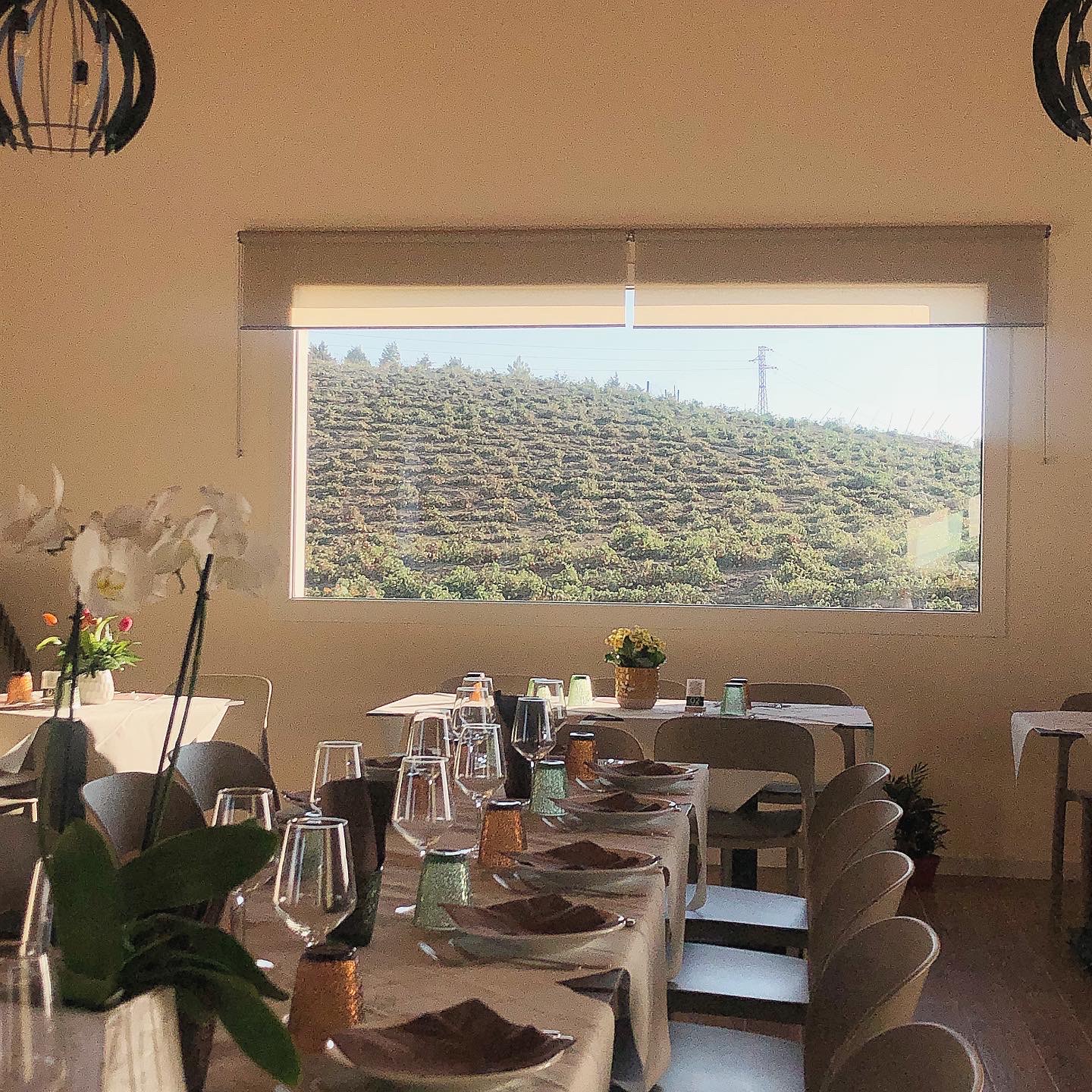


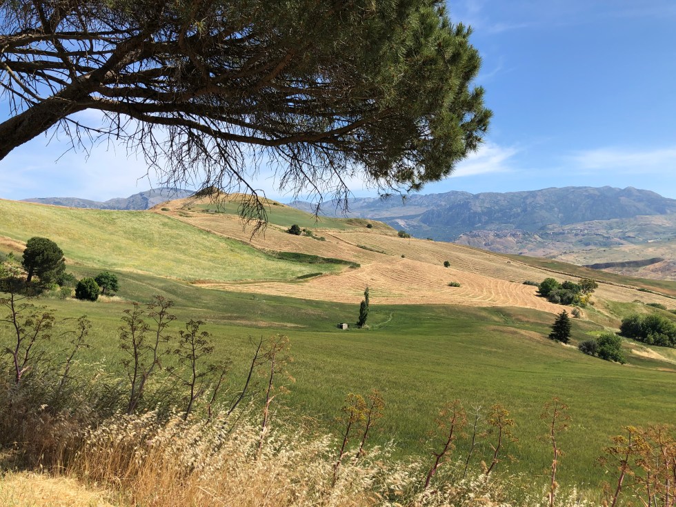


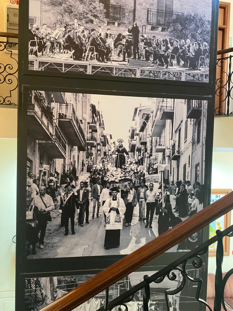


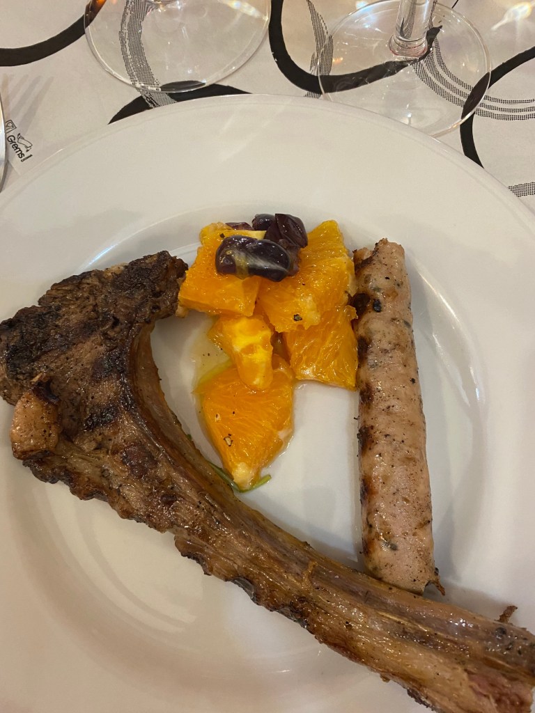


You must be logged in to post a comment.